An LED video wall controller connects a video source to the receiving system in an LED screen. An all-in-one unit can combine video processing, scaling and LED sending functions. To choose one for a rental wall, first calculate the cabinet pixel layout, then check the controller’s output limits, input formats, receiving-card compatibility and required backup paths.
Total pixel capacity can rule a configuration out. It cannot, by itself, approve it. A processor may have enough total capacity yet still be unsuitable for a very wide screen, a particular port layout, the intended input signal or the installed receiving cards. These five checks turn those conditions into a practical selection process.
1. LED video wall controller explained: follow the signal
Equipment names overlap. A quote might say “LED screen processor,” “sending box” or “all-in-one controller.” Ask which functions the proposed equipment actually provides:
- Source or player: a computer, media server or other playback system supplies content at a specified resolution and frame rate.
- Video processing: accepts supported input signals and provides the specified scaling, switching or picture layers. The available functions depend on the device and operating mode.
- LED sending: distributes screen data to the compatible LED receiving system through the configured outputs.
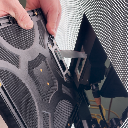
- Receiving cards: work with the cabinet’s module electronics and configuration to display the assigned image area.
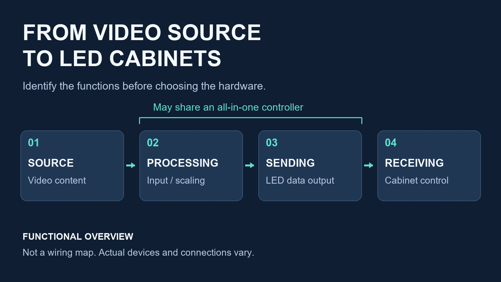
A sending device that lacks the required scaling needs an appropriate upstream content or processing arrangement. An all-in-one controller can simplify that arrangement when it provides the required inputs and processing. Neither name guarantees playback storage, multi-window support, a particular input timing or backup capability.
The sending and receiving stages must also be compatible. Share the existing controller and receiving-card identities, firmware information and configuration files when discussing reuse. Matching a connector or a brand name alone is insufficient to confirm the complete system.
2. Calculate the wall from cabinet pixels
Before choosing a video processor for an LED wall, establish the screen’s native pixel width and height. Use the actual cabinet resolution and orientation rather than dividing dimensions by a rounded pixel-pitch label.
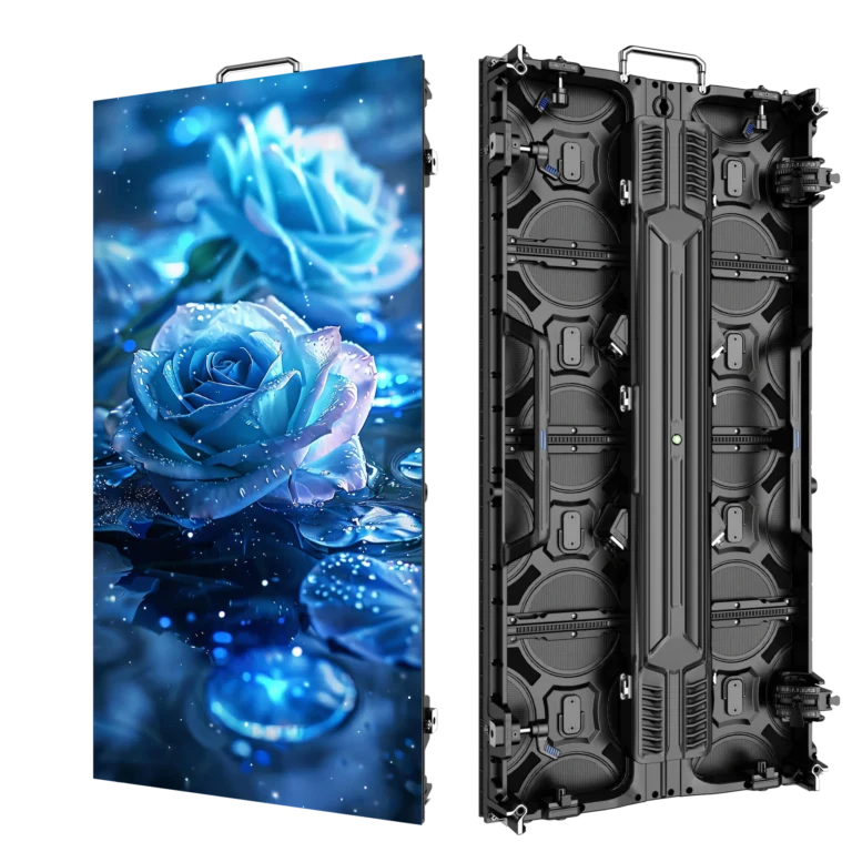
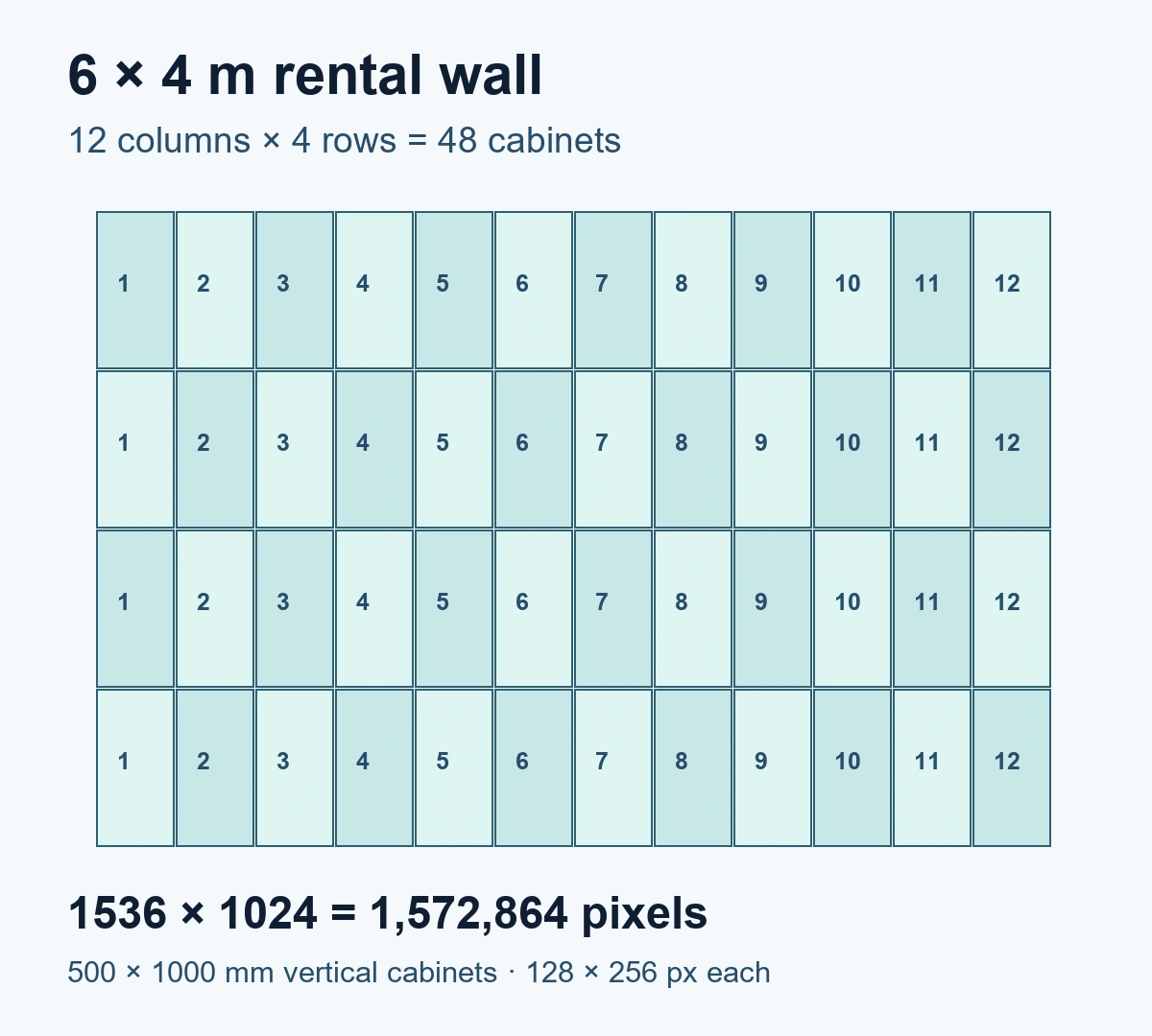
The P3.91 cabinet used in the following examples measures 500 × 1000 mm and has 128 × 256 pixels in vertical orientation. A 500 × 500 mm cabinet has 128 × 128 pixels. For a 6 × 4 m rectangle made from the larger vertical cabinets:
- Columns: 6 m ÷ 0.5 m = 12.
- Rows: 4 m ÷ 1 m = 4.
- Cabinets: 12 × 4 = 48.
- Pixel width: 12 × 128 = 1536; pixel height: 4 × 256 = 1024.
- Total load: 1536 × 1024 = 1,572,864 pixels.
The same method gives the following layouts. These are planning calculations, rather than measured projects or approved controller configurations.
| Wall size | Cabinet grid | Cabinets | Native resolution | Total pixels |
|---|---|---|---|---|
| 4 × 2 m | 8 × 2 | 16 | 1024 × 512 | 524,288 |
| 6 × 4 m | 12 × 4 | 48 | 1536 × 1024 | 1,572,864 |
| 8 × 4 m | 16 × 4 | 64 | 2048 × 1024 | 2,097,152 |
| 10 × 5 m | 20 × 5 | 100 | 2560 × 1280 | 3,276,800 |
If the cabinet resolution, orientation or combination of sizes changes, recalculate both dimensions. The LED wall calculator can help with cabinet geometry; controller suitability still requires the checks below.
3. Reject configurations that exceed output limits
Compare the calculated wall with the exact controller’s documented total capacity and width/height limits. Then check how that load can be assigned to the available outputs in the intended operating mode.
For a specific example, the official standard NovaStar VX1000 specifications, V1.4.0, list a total loading capacity of 6.5 million pixels, ten LED Ethernet outputs, a maximum width of 10,240 pixels and a maximum height of 8192 pixels. These figures apply to that standard model. Width and height are separate limits; multiplying them does not give the unit’s total capacity.
A configuration that fails immediately
A native 3840 × 2160 wall contains 8,294,400 pixels. That exceeds the stated 6.5-million total, so a single standard VX1000 is ruled out for driving that complete native canvas. The ability to accept a supported 4K input does not change the output limit.
A configuration that still needs confirmation
The 10 × 5 m example contains 3,276,800 pixels at 2560 × 1280. It is below those total, width and height limits. That clears those initial checks; it does not confirm the final configuration. The remaining questions are:
- Output allocation: can the actual receiving-card and cabinet layout be mapped across the outputs within each output’s permitted load and dimensions?
- Operating conditions: do the documented limits apply at the intended frame rate, bit depth and device mode?
- Processing needs: are the required source switching, scaling and simultaneous pictures available in that mode?
- Receiving system: are the supplied receiving hardware, firmware and cabinet parameters supported?
- Backup allocation: does the proposed backup arrangement leave the required primary loading and connections available?
Shape can rule a wall out even when its total is acceptable. For example, 100 of these cabinets in one horizontal row would form a 12,800 × 256-pixel canvas: still 3,276,800 pixels, but wider than the standard VX1000’s stated 10,240-pixel limit. The same number of cabinets can therefore produce a different selection result.
Do not apply a universal pixels-per-port figure or a fixed spare-capacity percentage to every LED video wall processor. Use the specific device documentation and the proposed system layout.
4. Match the source and define each backup path
Keep input format separate from screen resolution
A compatible high-resolution source can be scaled to a smaller LED canvas. It does not require the physical wall to have the source’s native resolution. Equally, an input connector’s name does not establish support for every resolution and frame rate that connector can carry.
Specify the source resolution, frame rate, interface and simultaneous-picture requirements. Confirm the supported timing and processing mode before treating the proposed LED video wall scaler or controller as suitable. Agree how the content should fit the wall, including any crop or unused area.
Panel refresh rate is another separate quantity. A 7680 Hz display specification does not mean a controller accepts 7680 video frames per second, and it does not guarantee clean footage with every camera setting. Camera-facing use needs the actual screen, control configuration, content and intended camera conditions considered together.
Ask what the backup actually protects
Configuration recovery, input backup, output-port backup and whole-device backup solve different problems. The standard VX1000 user manual, V1.4.0, documents separate configuration and backup procedures; other systems must be checked against their own documentation.
- Saved configuration files help restore settings. They do not automatically take over a live failed signal path.
- Input backup concerns the selected primary and backup source/input arrangement.
- LED output-port backup concerns specified downstream data paths, with supported receiving hardware, mapping and connections.
- Whole-device backup concerns failure of the primary control device and requires a suitable second-device arrangement.
Have the supplier identify which failure each proposed arrangement covers, what hardware and wiring it needs, and how the agreed failure cases will be checked. A statement such as “supports redundancy” does not establish protection for every component or guarantee an interruption-free show. For configuration and handover detail, use the LED video wall installation guide.
5. Confirm the processor configuration in the quote
The useful comparison is the complete agreed configuration. A processor name or screen area alone leaves important differences unresolved. Ask for these items to be identified and marked as included, optional, existing equipment or outside the supply:
| Item | What to confirm |
|---|---|
| Controller | Exact supplied model/version, operating mode and the documented limits used for the proposed wall. |
| Receiving system | Receiving-card identity, compatible firmware and cabinet/screen configuration responsibilities. |
| Input connection | Intended source formats and any required adapters or additional processing equipment. |
| Signal transmission | Required cable types, lengths and any specified long-distance transmission equipment. |
| Backup arrangement | Covered failure paths, necessary spare devices/connections and agreed checks. |
| Configuration and acceptance | Files to be delivered, who configures the system and what the agreed acceptance covers. |
For the wider screen package, refer to the existing LED wall system cost and quote worksheet. It covers the full-system scope beyond the processor configuration.
Send the information needed to check your system
When discussing a P3.91 outdoor rental LED display system, include the wall dimensions, cabinet sizes and native resolutions, intended layout, existing controller and receiving-card details, source format, simultaneous-picture needs, transmission distance, backup requirements, quantity and destination.
Those details support a specific compatibility review and a clear supply list. If you intend to reuse a controller, include its exact identity and available configuration information before assuming it can operate the new cabinets.