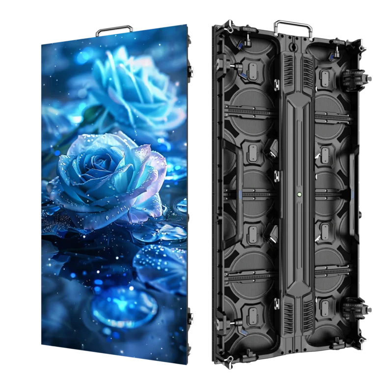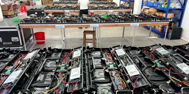
A dark module-sized rectangle does not, by itself, prove that an LED module has failed. First identify how much of the wall is affected, then distinguish a connection or cabinet-side fault from a faulty module. Once a complete module fault has been confirmed, a matching spare can replace the assembly.
This guide addresses LED screen problems on professional direct-view rental walls. It starts with fault-location checks, then follows a real P3.91 workshop sequence for replacing one completely dark module. The six photographs show the fixing points, disconnection, replacement connection and refastening of the demonstrated screw-fastened design.
LED screen problems: where should troubleshooting start?
Record the affected area before disturbing connections: the whole wall, a cabinet, a connected group, or one module. Photograph the symptom and note whether it appeared after transport, setup, a connection change or a configuration change. That information helps a technician choose the next check; the shape alone is not a diagnosis.
| What you see | What to distinguish | Useful next check |
|---|---|---|
| Entire wall is black | Source/processor state, screen output and shared power or signal paths | Check the selected source, any blackout setting and the documented system status. Have the responsible technician check shared distribution and signal paths before opening individual modules. |
| One cabinet or a connected group is dark | Cabinet power, inter-cabinet links, receiving hardware or another shared path | Locate the last working and first affected cabinets. Check their documented connections and status indicators; establish whether the fault follows a common feed. |
| One complete module is dark | Its local power/data connection, cabinet-side output or the module assembly | Isolate the affected cabinet before internal connection checks. Confirm the module-specific wiring and matching hardware before deciding to replace the assembly. |
| Lines, blocks or flicker affect part of the picture | Connection integrity, module electronics or a wider signal/configuration issue | Record whether the artifact stays within one module or crosses cabinet boundaries. Use the equipment’s diagnostic procedure to distinguish the paths. |
| A module lights but its color or brightness differs | Spare identity, settings or an optical-matching issue | Check the replacement identity and applicable records. A lit but mismatched area requires a different investigation from a completely dark module. |
For several LED screen issues, the useful first distinction is a shared fault versus a local fault. Several dark cabinets should prompt investigation of their common paths. Replacing individual modules without that distinction can leave the actual problem untouched.
Stop the routine checks if you find repeated protection trips, damaged wiring or signs of overheating. Electrical fault measurements and work on power supplies belong with qualified personnel following the equipment documentation.
Why can one module be dark while its neighbors work?
A working neighboring module shows that part of the system is operating. It does not prove that the dark position receives the correct power and data, or that every cabinet output is healthy.
The fault may sit in a local connection, a cabinet-side output or the module itself. With the affected cabinet isolated, a technician can check the documented connector positions, seating and visible cable condition. Any substitution used to distinguish these causes must follow the exact hardware documentation; an apparently similar connector is not permission to move a cable to an arbitrary port.
If the cause is a loose connection, address that connection. If diagnosis confirms the module assembly is faulty, proceed to a matching replacement. If the cause remains uncertain, keep the fault record and seek technical support rather than treating a rectangular black area as proof.
When does complete module replacement make sense?
Replacing a whole module and repairing its individual components are different jobs. A module swap removes the display subassembly and installs a compatible spare. Component-level repair investigates items such as LEDs, driver electronics or the circuit board on a suitable repair bench.
The workshop example below concerns one completely dark module, replaced as a complete assembly. It does not demonstrate lamp-bead soldering or establish a universal cause for dark modules.
Prepare the correct spare and service access
P3.91 describes pixel pitch; it is not a compatibility specification. Match the spare to the cabinet’s documented module version, mechanical fixing arrangement, electrical interfaces and configuration requirements. Keep the original order and batch information available, but do not assume that a matching label alone proves interchangeability. Our LED display spare-parts matching guide explains those selection checks.
The following example uses rear access and screw fixings. It does not apply automatically to magnetic modules or another locking mechanism. Check the access route for your exact cabinet; the front versus rear service comparison explains why the installed access arrangement matters.
How to replace an LED display module: the P3.91 example
Start only after the fault has been assessed and a matching spare is ready. Work from a stable, accessible service position and support the module throughout removal and refitting. This procedure replaces the module within its cabinet; it does not involve releasing structural cabinet or rigging hardware.
Before disconnecting or reconnecting module wiring, switch off and isolate the affected cabinet according to its service instructions. Restore power only after connections and fixing are complete and personnel are clear. The adjacent cabinets visible in the workshop photographs remained powered; their illumination does not establish that this module supports live replacement.
1. Locate the twelve fixing points
Use the marked rear-layout image to locate the fasteners before loosening them. The twelve numbered positions belong to the specific P3.91 module demonstrated here. Other P3.91 designs may use different fixing arrangements.
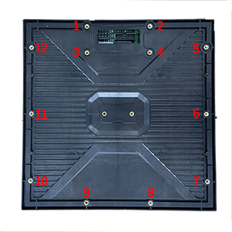
2. Support the module and release its screws
With the affected cabinet isolated, access the module fixings from the rear. Support the module so that it cannot fall or hang from its wiring as the fixings are released. Use assistance where the service position requires it.
Remove the twelve module screws with a correctly fitting tool, following the cabinet’s service method. Retain the screws for refitting; do not force damaged fasteners or improvise a torque setting.
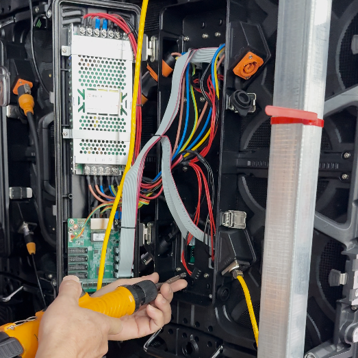
3. Disconnect the faulty module
Following the cabinet’s removal path, ease the supported module far enough from its seat to access the connections without straining the cables. Record the connector positions and orientation before disconnecting them.
Handle connector bodies rather than pulling on ribbon conductors or power wires. Disconnect the applicable module wiring using the exact service instructions. The photograph shows the grey ribbon connection; it does not define every connector fitted to other versions.
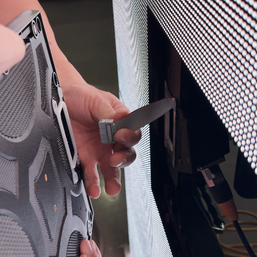
Set the removed module aside and label its cabinet position and reported fault for follow-up. Keep it separate from verified working spares.
4. Connect the matching replacement
Bring the checked replacement to the opening and support it while reconnecting the applicable wiring. Match each connection to its documented position and orientation; do not force a connector or substitute an unverified pinout.
Follow the equipment’s prescribed connection order. Keep the wiring clear of the seating surfaces so it will not be trapped when the module returns to position.
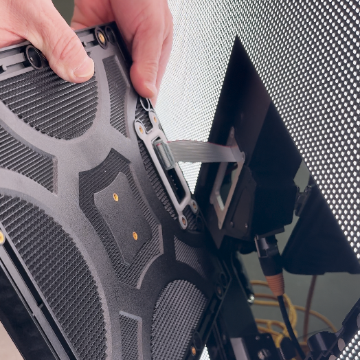
5. Seat the module in the cabinet
Guide the replacement into its correct orientation and mounting position. Check that its edges align with the neighboring modules and that the cables remain clear of pinch points. Do not use the screws to pull an incorrectly seated module into place.
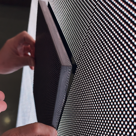
6. Refasten the twelve screws
Keep the module supported and correctly seated while refitting the twelve screws from the rear. Secure them using the manufacturer’s method and specified settings, where provided. Avoid overtightening or leaving a fixing loose.
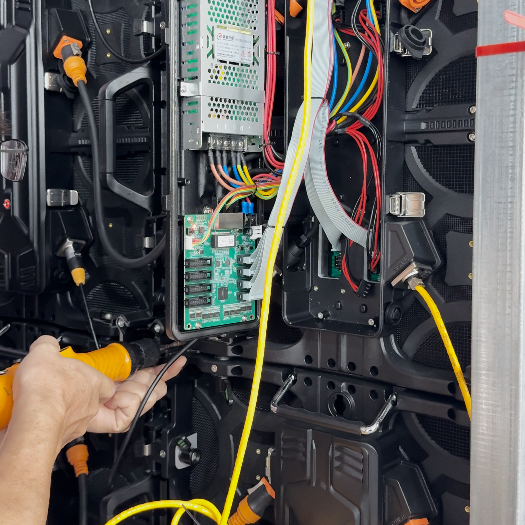
Check that the assembly is secure, the wiring is clear and the cabinet is ready to close in accordance with its instructions before restoring operation.
What should you check after LED display module replacement?
In this workshop example, the matching replacement lit normally once correctly connected. For a service procedure, complete and secure the assembly before restoring power; illumination alone is the first recovery check.
Then check the whole replaced area for missing lines, flicker or displaced content. Look at its edges for seating or alignment problems, and compare it with neighboring modules under the operating content. If the service plan calls for solid-color or grayscale patterns, use those checks as well. Complete the documented return-to-service checks before releasing the wall for use.
A module replacement does not automatically require full-wall recalibration. If brightness or color remains abnormal, investigate the replacement identity, applicable settings and calibration records for that system. Do not assume that every discrepancy is a calibration problem, or that sharing a production batch guarantees an invisible match.
What if the replacement is still dark?
Isolate the affected cabinet again before checking internal connections. A matching replacement that also stays dark is a reason to revisit the local connection and cabinet-side path. It does not justify repeatedly changing modules, trying undocumented ports or loading an unknown configuration file.
For support, record:
- The cabinet model, pixel pitch and available order or serial reference.
- The affected area and whether the symptom changed after replacement.
- Clear front/rear module photographs, including available version and identification labels.
- The sending/receiving system details and any relevant recent setup changes.
Send those details to WUYESTAGE for a configuration and replacement-parts discussion. The information helps distinguish a module-selection question from a connection or wider system fault.
For rental companies and distributors evaluating new equipment, review the service access and spare-parts arrangement alongside the screen specification. Our current outdoor P3.91 rental LED display is one purchasing option to discuss. Confirm the proposed version, cabinet size and maintenance arrangement with the order.
Frequently asked questions
Does one dark rectangle always mean a failed LED module?
No. The same visible area can be affected by its local power or data connection, a cabinet-side output or the module assembly. Identify the fault before choosing a replacement, and isolate the affected cabinet before internal connection work.
Can any P3.91 module replace another P3.91 module?
No. The same pixel pitch does not establish matching dimensions, fixing points, electrical connections or configuration. Use a documented matching spare or a replacement whose compatibility has been confirmed for the exact cabinet version.
Do I need to recalibrate the wall after every module change?
Not automatically. In this example, the matching replacement lit normally after connection. Check operation and visual consistency, then investigate any remaining abnormality using the system’s applicable settings and service records.