LED video wall installation brings together the cabinet layout, mounting system, electrical distribution, signal mapping and commissioning tests. The screen is ready for handover when the physical wall matches its control configuration, the agreed content displays correctly, and the next operator has the files and instructions needed to run it.
For a rental company or project buyer, the first job is to agree who supplies each part and who approves the installed system. This guide follows that process, then uses a 48-cabinet example to show how location IDs, data paths and handover records fit together.
It covers direct-view LED cabinets, rather than a tiled LCD video wall or decorative LED wall lighting. The mounting and electrical work must follow the supplied system’s documentation and the project’s approved design.
How to install an LED video wall: agree the sequence first
A practical sequence is confirm the site → approve the complete system → check the delivered equipment → assemble and connect → configure and test → hand over the working system.
Each stage needs an output the next team can use. A purchase list does not establish a support design; a wall showing a test pattern does not establish that the live content path works.
| Stage | Information or work to complete | Record to carry forward |
|---|---|---|
| Site and scope | Screen position, audience, environment, mounting method, accessible sides and local responsibilities | Site/layout revision and scope of supply |
| System approval | Exact cabinet version, support system, electrical design, processor, inputs and data allocation | Matching mechanical, electrical and signal documents |
| Delivery and assembly | Equipment identity, condition, approved support arrangement, cabinet position and alignment | Cabinet register and installation checks |
| Configuration | Receiver settings, cabinet mapping, source routing, scaling and agreed backup functions | Saved configuration and version record |
| Acceptance | Identification patterns, image checks, real content and required operating conditions | Test results and unresolved items |
| Handover | Files, recovery instructions, spare scope, service access and operator briefing | Controlled handover package |
Agree the division of work in the quotation. The cabinet supplier can confirm the supplied cabinet configuration and documentation. The project’s installer, electrical team and responsible designer must confirm the site work within their scope. Do not leave the support structure or power distribution unassigned because the cabinets have already been ordered.
1. Confirm the cabinet and mounting method together
For an LED wall installation, establish the required image size, viewing conditions, indoor/outdoor environment, installation duration and whether cameras will be used. These inputs affect the cabinet, structure and control system you need to review.
Ground-supported, flown and wall-mounted arrangements impose different requirements. A rental cabinet’s hanging or stacking capability does not mean it is approved for any truss, wall bracket, base or suspension point. Match the exact cabinet and attachment system to the site design, including the loads and outdoor conditions the responsible project team must assess.
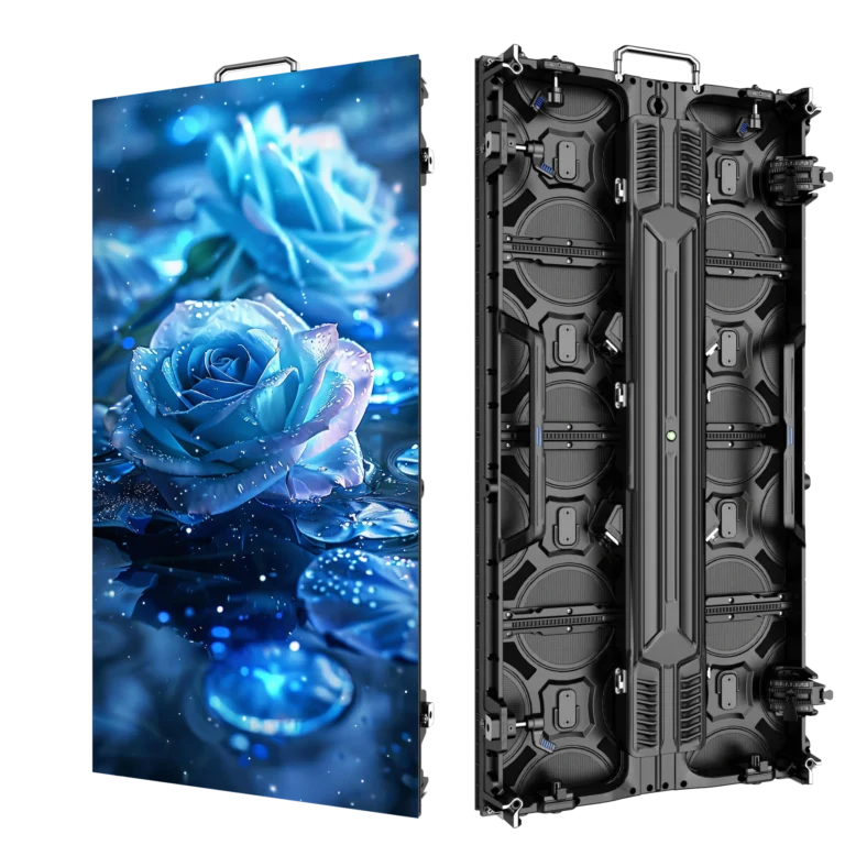
The P3.91 500×1000 outdoor rental LED display is a hanging/stacking product reference. Its 500×1000mm cabinet has a 128×256-pixel matrix. The front and rear views below identify the cabinet format being discussed.
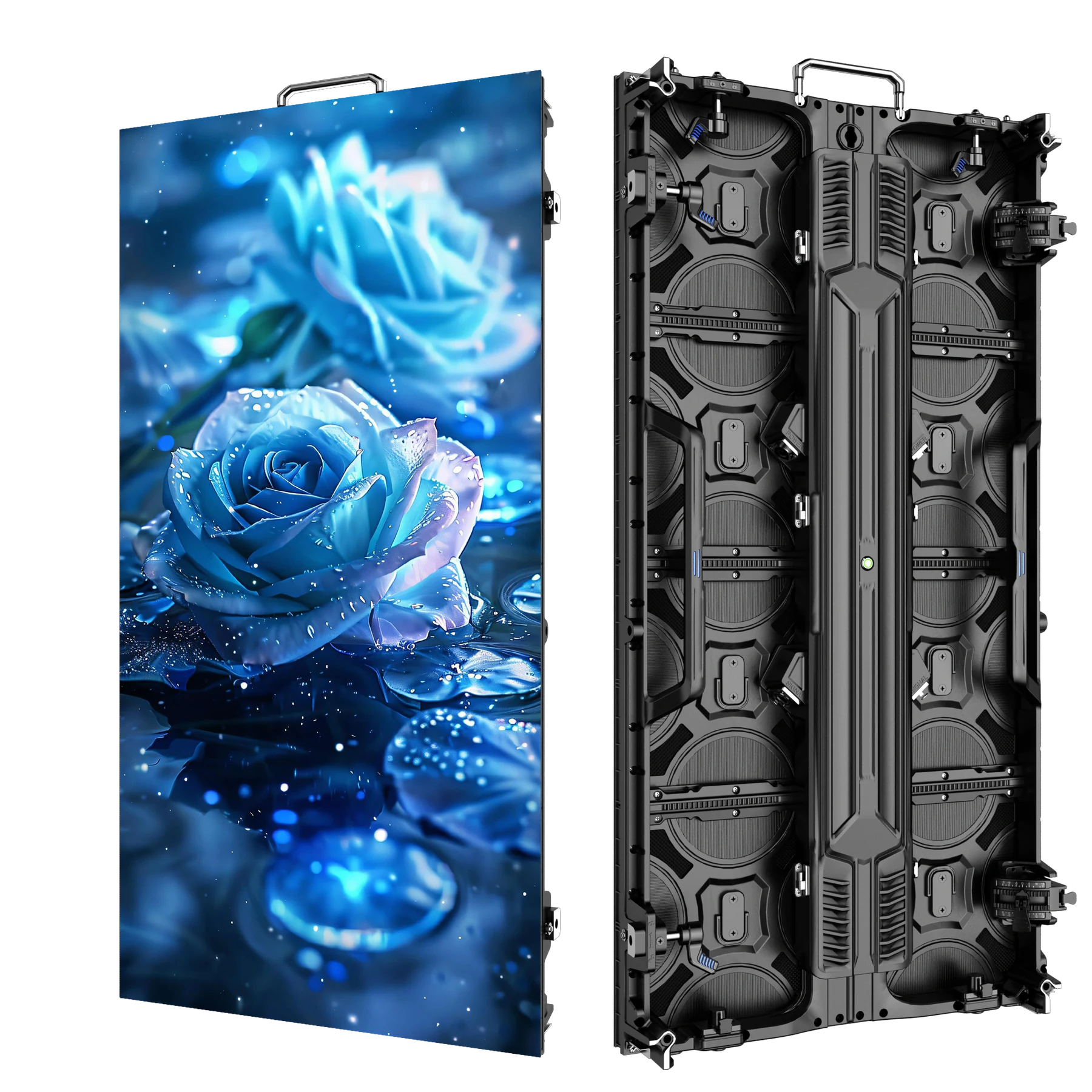
Match the cabinet version and attachment hardware to the project drawings before assembly.
For the example used here, a 6×4m wall contains 12 columns × 4 rows = 48 cabinets, giving 1536×1024 native pixels. Use the LED wall calculator for the underlying size, quantity and pixel calculations. That layout does not establish the mounting capacity, circuit allocation or processor suitability.
2. Resolve service access before the wall is assembled
Maintenance access belongs in the installation layout. Identify how a technician reaches the modules, power supplies, receiving hardware and connections, and how each required part can be removed once the support structure and scenery are in place.
The current P3.91 product is a rear-service reference. Its rear views show the central housing, handles and edge hardware that need to be considered alongside the actual support arrangement.
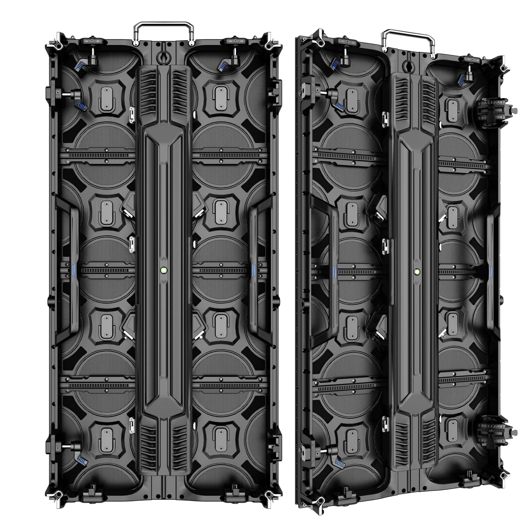
Review the rear arrangement against the installed support and component removal paths.
A visible gap in a photograph is not a confirmed working clearance. For a wall close to a building surface, determine which components still require rear access before approving the location. Our front vs rear service guide provides the component-by-component review.
3. Check the delivery, assemble and connect to the issued drawings
Before assembly, reconcile the received cabinet model, batch, quantities and accessories with the supply list. Record visible damage and exceptions before the equipment becomes difficult to access. Identify the agreed spare units separately from the installed quantity.
The installation team should establish the reference position and alignment using the supplied system’s procedure. Check the supporting arrangement, cabinet orientation, connection hardware and panel alignment as the wall is assembled. Do not use locks or improvised packing to force a cabinet into an unsupported position.
Keep the electrical and signal plans distinct. The electrical plan needs the actual equipment ratings, circuit allocation, connectors, protection, isolation and earthing requirements. Typical or average screen power is not a substitute for that design. Label the installed distribution so a cabinet location can be traced to its documented supply.
For data, record the sending device, output port, first cabinet and connection order. Record any converters or fiber links in the path. Connector appearance alone does not establish compatibility or an approved extension length. Qualified personnel should complete the required installation checks before energizing and commissioning the system.
4. Give every cabinet a location ID and a traceable data path
Use a clear viewing convention. In this example, R1C1 is the top-left cabinet when looking at the display from the audience side. Rows increase downward; columns increase to the right. A technician standing behind the wall must interpret the drawing from that stated viewpoint.
The location ID is separate from a cabinet’s serial or asset number. If the cabinet at R2C5 is replaced, the location stays R2C5; the equipment register records the replacement unit and any affected configuration or calibration information.
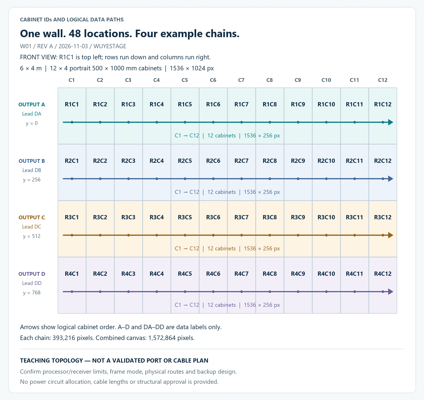
Example W01, revision A. Location and logical data-flow illustration only; confirm the actual port allocation and cabling for the supplied system.
The four chains below are a teaching topology. They do not approve four outputs on a particular processor. Check the actual device’s per-port capacity and supported loading dimensions, output mode, frame rate, receiving hardware, cable arrangement and backup requirements.
| Example output / lead label | First → last cabinet | Order within the row | Pixel origin x, y | Mapped area | Cabinet count |
|---|---|---|---|---|---|
| A / DA | R1C1 → R1C12 | C1 through C12 | 0, 0 | 1536×256 px | 12 |
| B / DB | R2C1 → R2C12 | C1 through C12 | 0, 256 | 1536×256 px | 12 |
| C / DC | R3C1 → R3C12 | C1 through C12 | 0, 512 | 1536×256 px | 12 |
| D / DD | R4C1 → R4C12 | C1 through C12 | 0, 768 | 1536×256 px | 12 |
Each row covers 393,216 pixels; together they cover 1,572,864. The arithmetic checks the example’s mapped area. It does not establish output compatibility. A power-circuit reference belongs in the separate electrical record for each location; A–D and DA–DD are data labels only.
Keep the map and actual cable labels synchronized. If a row is physically connected in reverse order, correct the documented mapping or cabling through the approved procedure. A readable image in the middle of the screen is not enough to prove every cabinet is in the right place.
5. Configure the receiver, wall layout and content path separately
An LED display installation needs the correct receiver settings for the supplied cabinet hardware and the correct screen connection map for the assembled wall. The content source and processor also need an agreed input, crop, scaling and output setup.
These settings are related, but they are not interchangeable. Daktronics’ NovaStar backup guidance distinguishes receiver-card configuration, screen-layout configuration and system configuration in its supported workflow. Preserve the appropriate exports for your actual hardware and software version; do not assume one file covers every setting.
CMS130, CMS260 and NovaStar VX1000 are project options for the P3.91 system, not automatically included processors. Select the actual unit from the complete wall, inputs and production requirements. For a VX1000 workflow, NovaStar’s user manual separately describes sending cabinet configuration, saving it to receiving cards and checking mapping. Its mapping function also depends on receiving-card support.
Do not treat a change visible on screen as proof that it has been saved for the next start-up. Follow the applicable save procedure, preserve the working exports and verify the agreed recovery behavior under controlled commissioning conditions.
Native wall resolution is not necessarily the input resolution
The example wall is 1536×1024, an aspect ratio of 3:2. A 1920×1080 source is 16:9. They can work together through an appropriate processor setup, but the scaling choice matters.
To fit that complete 16:9 image into the native wall without distortion, an illustrative centered fit is 1536×864, with 80 unused pixels above and 80 below. Filling the whole wall instead requires cropping or a differently prepared composition; stretching the source changes its proportions.
Test the real presentation, graphics and playback system. Check text, logos, captions and edge content rather than accepting only a colorful full-screen loop.
6. Commission with identification patterns and the actual show content
Agree the acceptance conditions before testing. Record the settings, content and result so the checks can be repeated after a replacement or configuration change.
| Check | What to observe | Evidence to retain |
|---|---|---|
| Cabinet identification | Every displayed ID matches the intended location and orientation; no missing or duplicated region | Map revision and identification-pattern photos |
| Image continuity | Grids and lines cross cabinet boundaries correctly; physical alignment and image mapping agree | Observed seams, offsets and corrective actions |
| Brightness and color | Agreed test patterns reveal inconsistent regions or visible defects at the operating setting | Pattern, brightness setting and result |
| Actual content | Source routing, aspect ratio, scaling, captions and edge content meet the agreed use | Source/output settings and content version |
| Required camera use | Footage meets the project’s agreed conditions | Camera, frame rate, shutter, screen settings and clips |
| Recovery and redundancy | Saved settings and any specified backup behavior operate as agreed | Procedure, configuration version and observed result |
These are checks to perform, not results for an installed WUYESTAGE project. Define tolerances and acceptance criteria with the supplier and project team. Treat defects and incomplete tests as open items with an owner and a retest condition.
For camera work, use the LED screen refresh-rate and camera checklist. A published refresh-rate figure alone cannot establish clean footage with every camera setting.
7. Hand over the files that match the working wall
The handover package should identify what is installed, how it is connected, which settings produced the accepted result and how the responsible team can recover them. Keep an accessible copy outside the controller or configuration laptop.
The following example record IDs show how to organize the 48-cabinet wall. They are document references, not software-import files or completed approvals.
| Example record | What it contains | What must match before handover |
|---|---|---|
| W01-LAYOUT-A | Front-view 12×4 layout, R1C1–R4C12, cabinet register | Physical locations and installed unit identities |
| W01-SIGNAL-A | A–D allocation, DA–DD leads, first cabinet and connection order | Actual ports, cable labels and saved screen map |
| W01-ELECTRICAL | Issued circuit schedule and location references | Installed distribution and project electrical checks |
| W01-CONFIG | Receiver exports, screen connection/system exports and relevant calibration data | Supplied hardware, firmware/software versions and accepted settings |
| W01-CONTENT | Source routing, native canvas, scaling/crop and operating presets | Actual input and production content |
| W01-TEST | Identification, visual, content and required recovery/camera results | Tested configuration revision and unresolved items |
| W01-SERVICE | Access documents, agreed spare scope, recovery instructions and support contacts | Exact installed version and operator responsibilities |
Keep firmware identity with the record; do not turn handover into an unplanned firmware update. Retain approved recovery files or references where supplied, and record compatibility requirements. A spare receiver or module should have an agreed configuration and replacement procedure, not just a part number.
When an accepted setting changes, update the relevant exports, map and test record together. Superseded files need a clear status so the next operator does not restore an earlier layout by mistake.
Send a project brief before requesting the installation supply
For an LED screen installation quotation, send the target width and height, indoor/outdoor conditions, viewing distance, mounting intention, installation country and local team’s scope. Include the content sources, camera use, service side, control/backup requirements and expected handover documents.
If the 500×1000 rental format suits the project, use the P3.91 product page to discuss the cabinet and system configuration. Confirm which structures, cables, processors, spares and documentation belong in the quotation. The goal is a supply package that the project team can install, commission and take over against the same agreed documents.
Frequently asked questions
What should be confirmed before LED video wall installation?
Confirm the site and environment, cabinet version, layout, mounting system, electrical design, service access, processor, input sources, data allocation and division of responsibilities. Agree acceptance and handover requirements before assembly.
Can I mount a rear-service LED wall directly against a wall?
Only approve a layout that preserves every required service route for the exact cabinet version. If the building wall blocks required rear access, revise the layout or select a documented configuration suited to the location.
Does the LED wall input have to match its native pixel resolution?
Not necessarily. A suitable processor can handle an agreed scaling or cropping arrangement. Confirm its supported modes and test the actual content so proportions, text and important edge information display correctly.
Why keep configuration backups if the screen already works?
The working image does not provide the files needed after a controller, receiver or laptop replacement. Preserve the appropriate receiver, layout and system exports, version information and recovery procedure, and verify the required recovery behavior before handover.