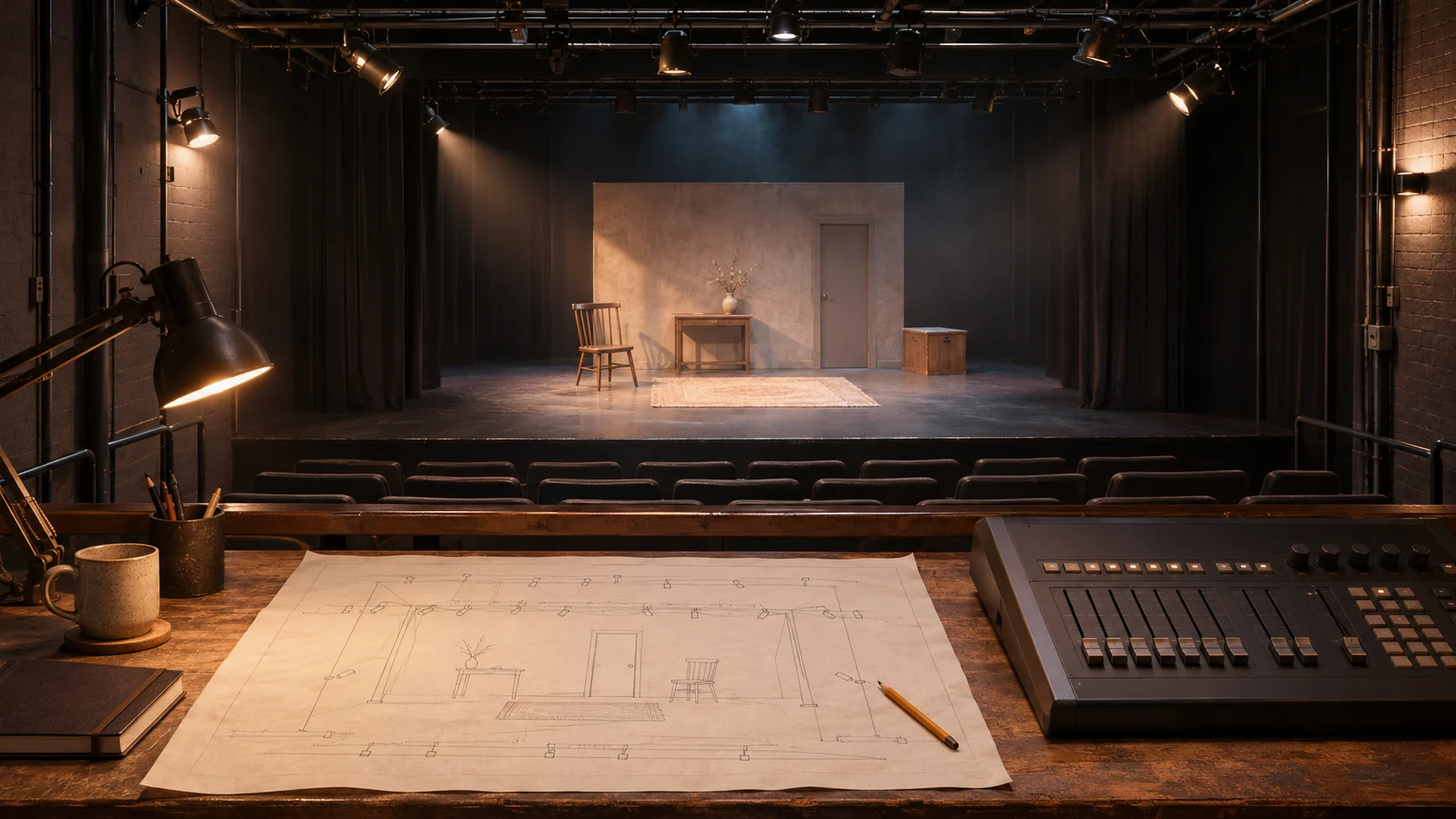
A lighting plot, also called a light plot, shows where lighting fixtures belong in relation to a stage and its hanging positions. The drawing connects each fixture to identifying information, while accompanying schedules hold the details needed to prepare, patch and check the rig.
The useful test is simple: pick one fixture on the drawing. Can another person find the same fixture in the equipment list and control patch without guessing?
This guide follows six fixtures through one drawing and three matching tables. It also includes blank records you can copy into your own production paperwork. For decisions about lighting purposes, venue conditions and installation planning, start with our theatre stage lighting design guide.
What is a lighting plot—and what belongs elsewhere?
In theatre, the overhead drawing is often called the light plan. “Light plot” can also refer to the wider paperwork package. IATSE Local 470’s reading guide distinguishes the plan, instrument schedules and channel hookup, and explains why their numbering must agree.
Keep three questions separate. The plan answers where the fixture is. The patch answers how the console reaches it. A cue sheet or show file describes what happens during the show. A symbol on the plan does not, by itself, specify a complete cue sequence.
An overhead view also cannot establish every height, clearance or beam angle. Where these affect placement, use a section or elevation with the venue information. Vectorworks’ light-plot guide explains how the plan and section work together. Software can help organize the documents; it cannot replace missing measurements.
How to read a lighting plot before following the symbols
First check the title block: production, venue, drawing title, author, issue date and revision. Confirm whether the sheet is an issued version or an earlier working copy.
Next establish orientation. In the example below, the audience is at the bottom. Upstage is toward the top. Stage left is the performer’s left when facing the audience, so it appears on the right side of this drawing. The centerline divides the stage into left and right halves.
Then check scale and units. A measured drawing should state both, along with its reference points. Our example is explicitly not to scale, with no dimensional units: it explains document relationships and cannot supply hanging distances. Do not measure a fixture location from its image pixels.
Finally read the legend. Lighting plot symbols are only useful when their meaning and nearby labels are clear. Identify the fixture type or model, the unit or fixture ID, the position, and any channel or patch notation. Symbols and label arrangements vary between projects. A circle in one drawing is not proof that another drawing uses the same fixture or control mode.
A theatre lighting plot example: six fixtures, one shared ID system
This teaching example has two nominal hanging positions: A, the downstage bar, and B, the upstage bar. All six units are RG-370 fixtures. Four use 21-channel mode and two use 148-channel mode. The different symbols distinguish those example modes; they are our legend, not a universal drafting standard.
These positions and quantities demonstrate paperwork. They are not a recommended complete theatre rig, an aiming design or an approved installation. A real design may need separate front light, side light and other fixture types.
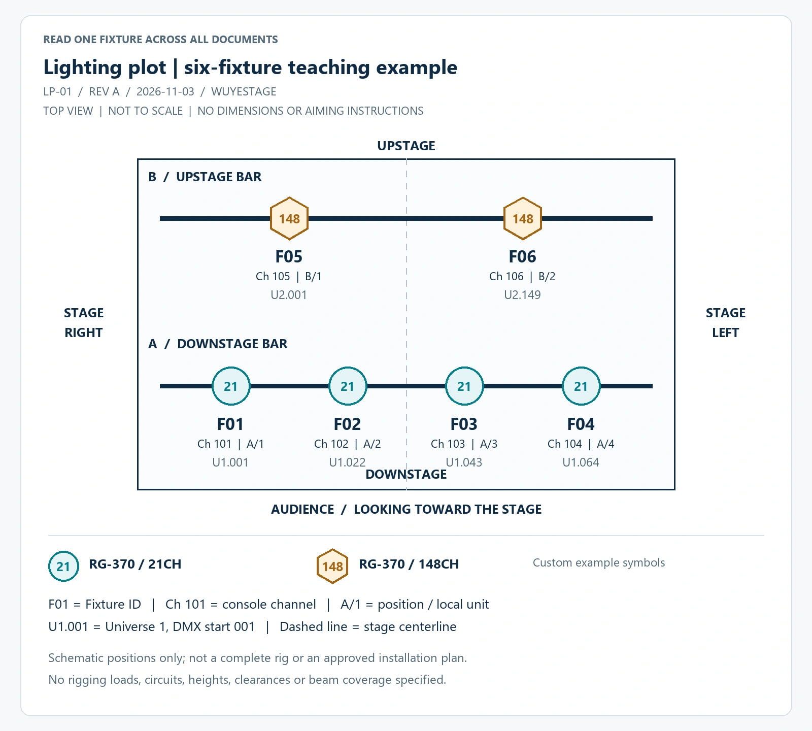
Example LP-01, revision A. Top view, not to scale; no dimensions or aiming instructions. Match F01–F06 to the tables below.
Table 1: Instrument schedule—find the physical unit
The instrument schedule organizes the fixtures by position and unit. Here, the globally unique Fixture ID is the shared reference across every document. The position unit number is a separate local sequence; A/1 and B/1 are different units.
| Fixture ID | Position / unit | Model | Selected mode | Console channel | Intended example role |
|---|---|---|---|---|---|
| F01 | A / 1 | RG-370 | 21CH | 101 | Downstage wash/effect unit |
| F02 | A / 2 | RG-370 | 21CH | 102 | Downstage wash/effect unit |
| F03 | A / 3 | RG-370 | 21CH | 103 | Downstage wash/effect unit |
| F04 | A / 4 | RG-370 | 21CH | 104 | Downstage wash/effect unit |
| F05 | B / 1 | RG-370 | 148CH | 105 | Upstage pixel-control example |
| F06 | B / 2 | RG-370 | 148CH | 106 | Upstage pixel-control example |
For an issued project schedule, add the actual focus/purpose and any required accessories, lens, color or other configuration fields. Conventional fixtures may also need dimmer and circuit information. The University of Minnesota Duluth’s lighting-schedule notes explain how schedules support inventory checks, focusing and troubleshooting.
Table 2: Patch and channel hookup—find the control assignment
The console channel identifies the fixture in this example’s console workflow. It is not the DMX start address, a dimmer number or a count of the fixture’s attributes. Console terminology varies, so agree on the labels before exchanging files.
The patch below is sorted by console channel and includes the universe, start address and inclusive end address. Universes are numbered from 1 here; confirm how the actual console, network output and gateway label them.
| Fixture ID | Console channel | Universe | DMX start | Footprint | DMX end |
|---|---|---|---|---|---|
| F01 | 101 | 1 | 001 | 21 | 021 |
| F02 | 102 | 1 | 022 | 21 | 042 |
| F03 | 103 | 1 | 043 | 21 | 063 |
| F04 | 104 | 1 | 064 | 21 | 084 |
| F05 | 105 | 2 | 001 | 148 | 148 |
| F06 | 106 | 2 | 149 | 148 | 296 |
Use end = start + footprint − 1. F06 therefore ends at 149 + 148 − 1 = 296. Each row stays inside its 512-slot universe, with no overlapping ranges in the same universe.
Universe 1 uses 84 slots, leaving 428 unassigned; Universe 2 uses 296, leaving 216 unassigned. The split makes the example easy to read. It is not a requirement: the combined 380-slot footprint could fit in one universe with suitable consecutive assignments. F01 and F05 can both start at 001 because they occupy different universes.
For a fuller explanation of address ranges and mode changes, see DMX channels and fixture planning.
Table 3: Equipment summary—reconcile the quantity and configuration
| Model / selected mode | Quantity | Fixture IDs | Preparation check |
|---|---|---|---|
| RG-370 / 21CH | 4 | F01–F04 | Confirm 21CH on fixture and matching console profile |
| RG-370 / 148CH | 2 | F05–F06 | Confirm 148CH and matching pixel-control profile |
| Total | 6 | F01–F06 | Six plotted symbols, six schedule rows, six patch rows |
This is a fixture-summary excerpt, not a complete shop order. It does not establish clamps, safety attachments, cable lengths, distribution, spare units or venue inventory. Add those from the actual equipment and venue requirements rather than deriving them from symbol counts.
Same fixture model, different patch footprint
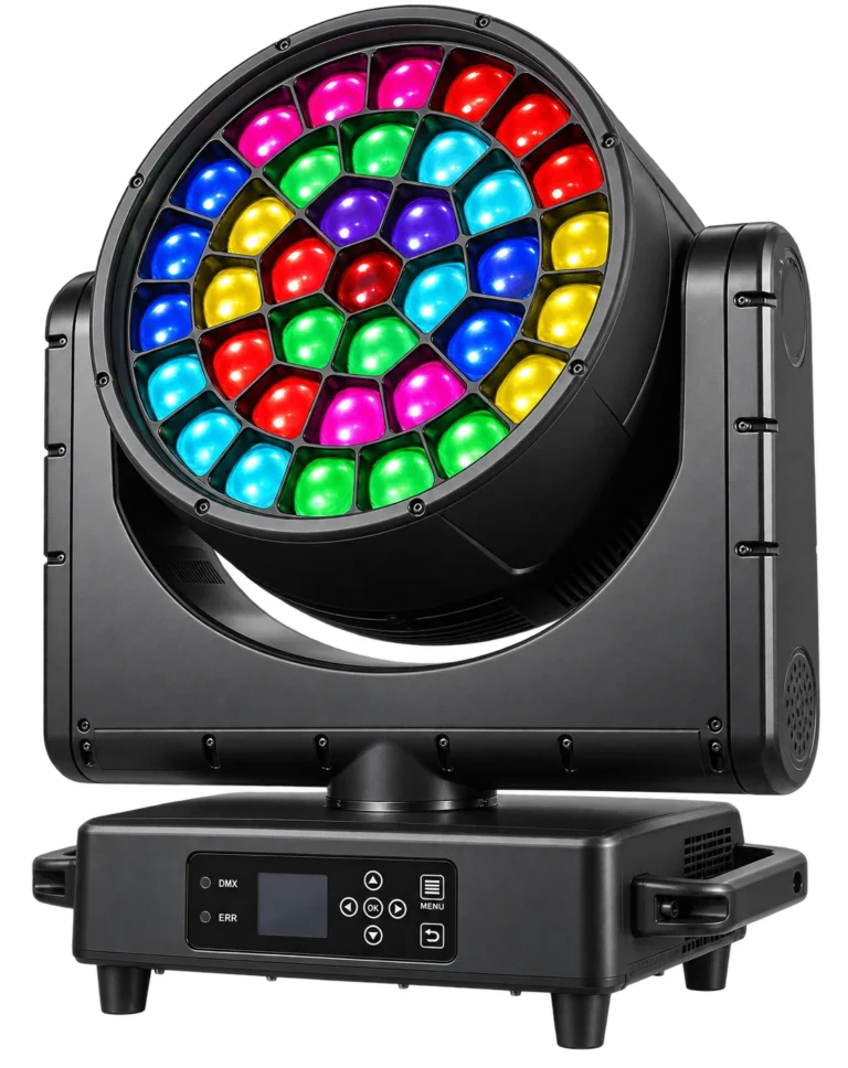
The RG-370 37×40W IP65 bee eye moving head supports both 21CH and 148CH modes among its available modes. The example uses these two modes to show why the mode belongs in both the fixture schedule and patch.
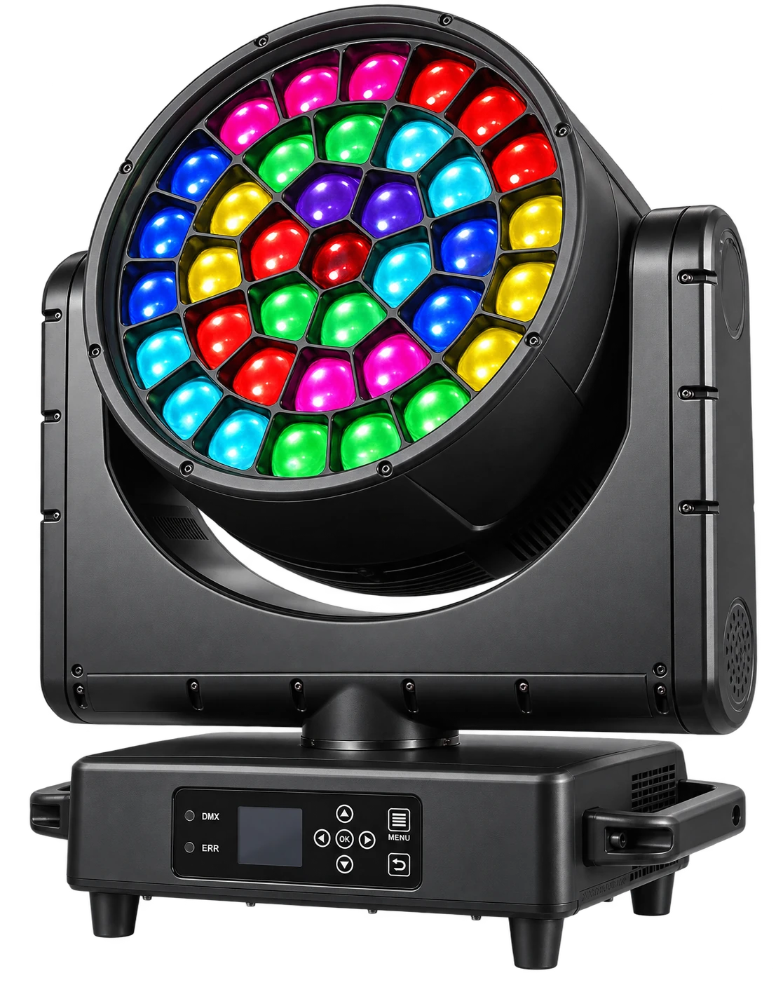
RG-370: confirm the selected control mode in the fixture menu and use the matching console profile.
A photo cannot confirm the mode currently selected in the menu, the console profile or the occupied DMX range. Before preparing the rig, match the fixture’s selected mode to the applicable channel chart and console profile. Do not substitute a similar-looking model’s manual.
For example, suppose F02 stays at Universe 1, address 022, but changes from 21CH to 148CH. Its new range is 022–169. It now overlaps F03’s 043–063 and F04’s 064–084. Keeping the model name and start address unchanged does not keep the patch valid.
The correction is to agree on the required mode, revise the affected address assignments and profiles, and issue the matching paperwork. Keep F02’s identity stable so the team can trace what changed.
How to make a lighting plot that survives revisions
Start with the venue’s current plan and measured reference points. Place the stage, scenery and available hanging positions before locating fixtures. Check the necessary height and angle information in section or elevation. The schematic above intentionally omits those project measurements.
Assign a stable Fixture ID to each unit, create a legible legend, and put the corresponding records into the schedule and patch. Export the documents at a readable size. A recipient should be able to follow an ID without zooming through overlapping labels.
Before issuing a revision, check three kinds of mismatch:
- Identity and quantity: every plotted unit has one matching schedule row and one patch row. An extra F07 in the equipment list needs a plotted location or an explicit spare designation.
- Configuration and control: modes agree, addresses remain within range, and unintended overlaps are resolved. A spare unit should not silently acquire a live patch assignment.
- Version: drawing, schedule, patch and equipment summary carry the same issue reference. Record the change and identify the files the new issue replaces.
If F03 moves from A/3 to B/3, update its position on the drawing and schedule. Its DMX assignment may stay the same if the control design permits; do not renumber everything automatically. If its mode changes, recheck its footprint even when its position stays the same.
Copyable lighting plot template
Use the following blank records as a starting point. Repeat the fixture row for every unit. These fields accompany a drawing; they do not turn an unmeasured sketch into a dimensioned plan.
| Document control | Fill in before issue |
|---|---|
| Production / venue | ______ / ______ |
| Drawing ID / revision / issue date | ______ / ______ / ______ |
| Prepared by / contact | ______ / ______ |
| View / stage orientation | ______ |
| Scale / units / measurement references | ______ |
| Symbol legend and label format | ______ |
| Matching schedule / patch / equipment-summary versions | ______ / ______ / ______ |
| Change note / superseded issue | ______ / ______ |
| Fixture ID | Position / unit | Model / mode | Console channel | Universe / start / end | Purpose / configuration notes |
|---|---|---|---|---|---|
| ______ | ______ / ______ | ______ / ______ | ______ | ______ / ______ / ______ | ______ |
Keep a separate quantity summary grouped by model and configuration, then compare its total with the drawing and individual records. Add venue-specific circuit, power and rigging documents as required. Qualified project personnel must confirm those systems; a lighting plot alone does not establish their capacity.
What to send when asking for fixture configuration and a quote
Send the current plot together with the fixture schedule, selected modes and quantity summary. Include the venue or application, installation country, indoor/outdoor conditions, control system and required delivery scope. Flag unresolved substitutions and accessories rather than leaving them implicit.
If RG-370 is being considered, use its product page to discuss the required fixture configuration. The supplier needs to know which modes and quantities the project requires; the venue and integration team still need to confirm placement, electrical distribution and rigging.
Frequently asked questions
What is a light plot used for?
A light plot communicates fixture positions and identifying information for preparing and checking a lighting rig. Its accompanying schedules and patch records connect those positions to equipment and control assignments.
Is a console channel the same as a DMX address?
No. In this example, console channel 105 identifies F05, which starts at Universe 2, address 001 and occupies 148 slots. The console identifier and DMX address serve different purposes.
Does a lighting plot include lighting cues?
The plan shows the fixture layout. Cue timing and changing lighting states are normally recorded in separate cue documentation or the show file. A paperwork package may contain both, but one does not replace the other.
Can I use this lighting plot as an installation drawing?
This example is not to scale and has no project dimensions, electrical design or rigging approval. Use it to understand the shared IDs and tables; obtain the current venue drawings and project-specific documentation for installation.